| Navigation | Equipment | Culbertson | White Cliffs | Great Falls | Gates of the Mountains | Three Forks | Beaverhead Rock | Pompeys Pillar | Terry |
Lewis and Clark in Montana — a geologic perspective
Expedition's Scientific Equipment
To Captain Meriwether Lewis esq. Capt. of the 1st regimt. of the Infantry of the U.S. of A
…The object of your mission is to explore the Missouri river, & such principal stream of it, as, by it's course and communication with the waters of the Pacific Ocean, whether the Columbia, Oregan, Colorado or any other river [which] may offer the most direct & practicable water communication across this continent for the purposes of commerce …
Beginning at the mouth of the Missouri, you will take careful observations of latitude & longitude, at all remarkeable points on the river, … & other places & objects … that they may with certainty be recognised hereafter. The courses of the river between these points of observation may be supplied by the compass … the log-line & by time, corrected by the observations themselves. The variations of the compass too, in different places, should be noted …
The interesting points of the portage between the heads of the Missouri, & of the water offering the best communication with the Pacific ocean, should also be fixed by observation, & the course of the water to the ocean, in the same manner as that of the Missouri …
"Given under my hand at the city of Washington this 20th day of June 1803."
[signed] Thomas Jefferson, President
Thomas Jefferson envisioned the Lewis and Clark Expedition as a scientific expedition, but also hoped it would find a practical commercial route to the Pacific. Not only did Jefferson want the information that expedition obtained, he wanted an accurate map of the country through which it passed. To make an accurate map of such a large area would require accurate locations of river junctions, rapids, falls, mountain passes, and native settlements. Jefferson knew that such a map could not be made from a survey using just a magnetic compass and estimated distances. The solution — find the latitude and longitude of important points along the route and adjust the compass survey to them.
Latitude is the angular distance north or south of the equator. The latitude at the equator is 0°; at the poles it is 90°.
Longitude is the angular distance east or west of the Prime Meridian (the north-south line through Greenwich, England); the longitude there is 0°. From the Prime Meridian the longitude increases eastward (east longitude) to 180° and also westward (west longitude) to 180°.
The intersection of a parallel of latitude with a meridian line of longitude marks the location of a unique spot on the surface of the earth.
In the early 19th Century, latitude and longitude usually were determined from celestial observations taken with a sextant or octant and chronometer. Lewis purchased this equipment in 1803. He also received training in how to make celestial observations and calculate them. From this training Lewis taught William Clark. Clark already knew how to use a magnetic compass to survey and he had a talent for map drawing.
The expedition’s route survey would be made with a magnetic compass. The captains, therefore, also needed to make observations to determine how many degrees the compass needle pointed away from true north (that is, the magnetic declination). The celestial observations the captains took would fix the latitude and longitude of important river junctions and, by knowing the magnetic declination, the survey made with the magnetic compass between those points could be corrected to true north. From this, a cartographer could produce an accurate map.
Shown below are the scientific
instruments similar to the ones Lewis purchased in Philadelphia.
Accompanying each instrument is a brief description of its design
and its use.
| Sextant | ArtificialHorizon | Two-Pole Chain | Nautical Almanac | Chronometer | Circumferentor | Compass | Spirit Level | Nautical Almanacs | |
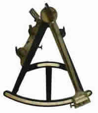
Octant Octants were used principally to determine latitude by measuring the angle between the sun and the horizon. The instrument had a simple “A” shape and its legs formed an angle of 45°, hence its name (from Latin octans = one-eighth). Because the octant’s two-mirror system used the principle of reflection, it could measure an angle of 90°; thus the instrument sometimes was also called a quadrant. Most were made of hard, tropical wood.
The index mirror was attached to the index arm, usually 12 to 14 inches long. The fore-horizon glass (half mirror-half clear glass) was affixed to the leg nearest the reflecting surface of the index mirror. A peep site was located opposite the horizon glass on the other leg of the “A”. The octant that Lewis and Clark used was also equipped with a back-horizon peep sight and mirror. This allowed them to measure the altitude of the sun when it was greater than 60° above the horizon (early April until late August along their route.)
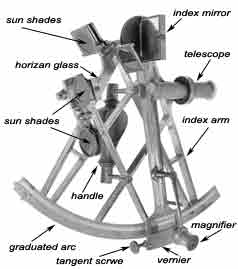
Sextant The sextant, invented about 1757, had the same “A-frame” configuration as the octant, but its circular arc spanned an angle of 60°, that is, a sixth (Latin sextant) of a circle, and its index arm usually was 9–10 inches long. With its two-mirror system the sextant could measure the angular distance between objects that were as much as about 120° apart. The sextant was made of brass and had a telescope for sighting.
Lewis and Clark used the sextant to measure the angular distance between the moon and sun or a star for longitude. They also used it for latitude when the sun's noon altitude was less than 60°. Although the sextant could measure an angle of up to 120°, the captains could not use the sextant to find the altitude of the sun when it was greater than 60° above the horizon because they needed to use an artificial horizon, which doubled the angle to be measured. Artificial Horizons Navigators at sea could determine the altitude of a celestial body by measuring the angle between it and the true horizon. Inland away from the sea or a large body of water, however, one rarely has a true horizon. Therefore, on land, it generally is necessary to use an artificial horizon. Lewis and Clark carried three different types of them. Each design had its own advantages depending upon observing conditions.
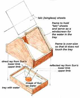
On bright days when the temperature was above freezing and the sun was being observed, Lewis and Clark commonly used a tray filled with water as an artificial horizon; the water made a level reflecting surface. The captains, however, used artificial horizons made from leveled mirrors when the temperature was below freezing. They also used them when observing stars because the image reflected from the mirrors was more distinct than from water. Robert Patterson, a Philadelphia mathematician
and astronomer, had devised several types of artificial horizons
using either a regular (single-coated) mirror or the double-coated
index mirror from a sextant. The mirror was cemented onto a wooden
ball and the ball was set in a wooden frame and adjusted by three
screws used as legs. It was leveled with the aid of a spirit
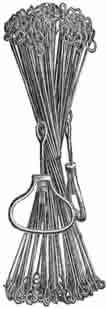
level. Two-Pole
Chain English
and American land surveyors of the 18th and early 19th
century generally Two-pole chain similar to one used by Lewis and Clark. Image from The Theory and Practice of Surveying, 1911 |
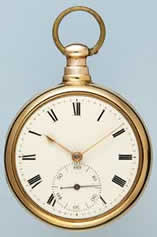
Chronometer A chronometer is a precise watch used to determine the time at which an observation is made. Chronometers usually are set to keep Greenwich Mean Time (the time at 0° longitude) because almost all nautical tables are based on Greenwich Time. Lewis and Clark’s chronometer, however, showed Local Mean Time and, because it stopped on several occasions and ran erratically at others, they needed to make special observations of the sun to determine the true Local Mean Time. Checking the chronometer’s time No chronometer kept perfect time; they either lost or gained time, though usually at a highly uniform rate. The captains knew that their chronometer lost time, but unlike most chronometers, its rate of loss was not consistent. To determine the chronometer’s error on Local Time, Lewis and Clark made observations called “Equal altitudes observations of the Sun.”
Using the sextant and artificial horizon, they would take three measurements of the altitude of the sun in the morning, noting the time shown by the chronometer for each. In the afternoon, when the sun was at the same altitude as it had been in the morning, the times again were recorded. The average of the times, after adjusting for sun’s changing declination, gave the time that the chronometer would have shown at noon. The difference between this calculated time and 12 noon was the “error of the chronometer.” From another Equal altitudes observation the next day or some days later, the captains could determine the chronometer’s daily rate of loss during that period of time.
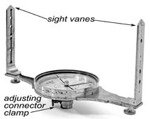
Surveyor's Compass or Circumferentor Lewis and Clark used the surveyor’s compass to record their direction of travel and determine the bearing of celestial objects such as the sun and stars. Because the bearings they observed were based on magnetic north, they often took observations of Polaris or the sun at the junction of major streams or other important points to determine the difference between magnetic north and true north. Most maps are based on true north, which does not change through time or with location.
The circumferentor was simply a six-inch-diameter magnetic compass, but was much more precise than the usual pocket or hiking compass and could be read to one-half of a degree. The circumferentor was equipped with front and rear sight vanes to help improve the observer’s ability to sight precisely on an object. On the underside of the compass housing was a receptacle to allow it to be fastened on a tripod or to a shaped pole that was placed firmly into the ground. Attached to that receptacle was a ball-and-socket joint that allowed the user to level the circumferentor with great accuracy. A spirit level would have been used in conjunction with the surveyor's compass to establish a level plane from which to work.
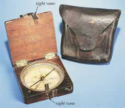
Pocket
Compass
Lewis purchased three pocket compasses for $2.50 each and also the compass shown in this picture. The pocket compasses were less cumbersome than the surveyor’s compass and were used to take the bearings when impractical to use the circumferentor and when traveling on land. This pocket compass was one of the few items that survived the journey. After the expedition returned to St. Louis, it was purchased by William Clark. The compass is on display at the Smithsonian Institution in Washington, D.C.
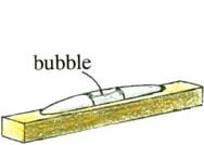
Spirit Level A spirit level is similar to a miniature carpenter's level, though made with greater precision. It was used to level the surveying compass (circumferentor) for precise angular measurements and to level a mirror to produce an artificial horizon when water was not used. Clark also used the spirit level as a hand level when he measured the height of the falls and rapids of the Missouri from Lower Portage Camp to White Bear Islands (see Great Falls of the Missouri). |
Nautical Almanacs, Requisite Tables, Mathematical Tables The captains’ celestial observations yielded nothing more than raw data. To determine latitude, longitude, and magnetic declination, their observations were processed with information provided by almanacs and tables.
Lewis carried with him The Nautical Almanac and Astronomical Ephemeris …
for the Year 1803, 1804 and 1805 (it is not certain that he had the 1806 almanac). The almanacs were published several
years in advance of the year 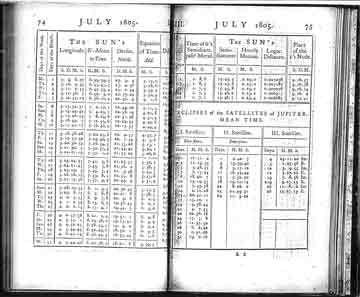 indicated on them and gave the celestial coordinates of the sun, moon, planets, and navigational stars at various increments of time at Greenwich, England.
A companion book to the Nautical Almanac was: Tables Requisite to be Used with the Nautical Ephemeris for Finding the Latitude and Longitude at Sea (Nevil Maskelyne). These books provided Lewis and Clark with valuable information on how and when to take observations, what corrections they needed to make to obtain valid results, and how to calculate geographic data from most of their observations. In addition, Lewis brought along a copy of A Practical Introduction to Spherics and Nautical Astronomy (Patrick Kelly) — a practical guide to spherical trigonometry and how to compute celestial observations and convert them into geographic information.
Image from The Nautical Almanac and Astronomical Ephemeris, 1805
| Navigation | Equipment | Culbertson | White Cliffs | Great Falls | Gates of the Mountains | Three Forks | Beaverhead Rock | Pompey's Pillar | Terry |